The dataflow in component-based systems, like what happens in Rock, is done asynchronously: components process data as it arrives. Since different processing chains have different computation times, it means that our carefully timestamped data will most probably arrive out-of-order at the components that need it.
Let’s see, as an example, the following processing chain:
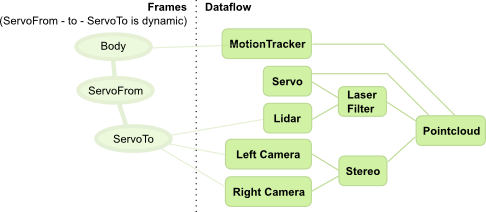
In this chain, sensors are fused through two paths. One path processes lidar data to remove outliers and body parts (laser filter). In another path, a stereo camera rig is used to generate a separate point clouds. The two informations are then merged to form a pointcloud that is represented in a frame that is centered on the body, but aligned to the world (i.e. a tabletop would look horizontal even if the robot’s body is on an incline). To achieve this, a motion tracker gives the pose of the body in the reference frame.
To add a bit more interesting effects, the lidar and cameras are mounted on a tilt unit with a single servo motor. The position of these sensors w.r.t. the body is therefore changing during operation.
If the robot moves during acquisition, it is obviously critical that the “right” association is made between the different channels. However, the different data processing paths have widely different processing times. Indeed, a realistic sample arrival diagram would look like:
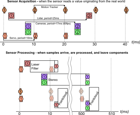
In this diagram, both times, the pointcloud processing must make sure that it is processing data that is properly associated in time. Moreover, this diagram does not take into account that sensors have different acquisition latencies. It would not be uncommon, in such a processing pipeline, that the first lidar sample arrives after the second motion tracker (or servo) sample.
In Rock, there is one piece of software that handles these problems in a common way: the stream aligner. As we will see later, this method has its drawbacks, and might not be right for your problem. However, it has shown to be a good solution in most cases.
Stream Aligner Principles
Rock’s stream aligner (in the drivers/aggregator package) ensures that data is processed in order by (1) queueing timestamped data, and (2) calling registered callbacks in the order of the timestamps.
The general principle is therefore that:
- one callback is registered for each data stream
- data is pushed as it arrives in the corresponding streams. The leading assumption is that, on each stream, the timestamps are monotonous (they don’t go back in time).
- the respective callbacks get called when it is time to process the relevant samples. This is done only when the stream aligner determined that no sample from other streams can arrive with an earlier timestamp then the one that is being passed to a callback.
We’ll now see how the decision is being made.
Period, latency and stream aligner timeout
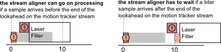
Let’s look at the example of the laser filter again:
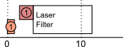
If, as this diagram shows, the laser filter starts processing as soon as the lidar sample arrives, it means that the stream aligner would, in this case, have determined that it is impossible that a motion tracker sample arrives in between the first motion tracker and first lidar samples.
With no additional information, however, the stream aligner would have to wait that another sample arrives on the motion tracker before processing the first laser sample:
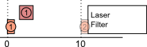
Which builds up latency …
To avoid this, the stream aligner allows to set a period parameter on each stream. This period parameter (which is also called lookahead in event-based systems) is the time after a sample in which there is a guarantee that no other sample arrives. It is called period in the stream aligner as it is the value of the input periods, for periodic inputs such as common robotic sensors. When visualizing the period, the above example looks therefore like:
Because processing based on the stream aligner is based on the fact that samples are passed in-order, the stream aligner must drop samples that arrive “in the past”, i.e. that arrive with an earlier timestamp that the last sample “played” by the stream aligner. So, it is better to give a period that is lower than the actual sensor period so that the aligner does not drop samples unnecessarily.
In order to not wait forever for samples that will never arrive (lost samples), the stream aligner also allows to set a timeout parameter, which is the highest latency that the aligner would allow to build up. When the latency induced by the stream aligner is higher than this value, the aligner starts playing queued samples regardless of the fact that, in principle, some samples should arrive on the other streams. If these samples do arrive anyway, they will therefore get dropped. This parameter is therefore a trade-off between the maximum latency that the processing chain can accept and how exact the result needs to be.
Using the stream aligner
As in all of Rock, the stream aligner is implemented as a pure C++ library that can be used outside of Rock’s component framework. The API of this library will not be detailed in this documentation. Go to the drivers/aggregator package documentation for more details.
The most interesting usage of the stream aligner is within oroGen components. Rock provides an oroGen plugin that extends the oroGen specification and generates code and oroGen interface elements to control the stream aligner. The following page will explain the usage of this plugin. The next page will then detail how it can be parametrized and monitored in practice.