In this page, we will detail – as an example – how the ROS prosilica camera output can be displayed using vizkit. (To use the camera with ROS check the tutorials at http://ros.org/wiki/prosilica_camera/Tutorials/)
To be able to use Rock’s visualization tools, add the following to the layout section of autoproj manifest (autoproj/manifest):
- gui/vizkit
Now, update and build.
Step 1: Data Type Convertion
We want to be able to convert the ROS image message into its Rock equivalent, the base::samples::frame::Frame type.
Since base::samples::frame::Frame is declared in the base/orogen/types oroGen project, we go there (base/orogen/types/base.orogen) and add the necessary ROS-to-Rock mapping declaration (if not yet present):
typekit.ros_mappings '/base/samples/frame/Frame' => 'sensor_msgs/Image'
And run amake once
amake
For the conversion between ROS and Rock to work we then have to fill in conversion functions. Stubs for the conversion functions are automatically generated, i.e. if there was no ROS mappings in the package before, just edit typekit/ROSConvertions.cpp. Otherwise, we have to copy the relevant signatures from templates/typekit/ROSConvertions.hpp and .cpp into the corresponding files in the typekit/ subfolder.
namespace ros_convertions {
    ...
    void toROS( sensor_msgs::Image& ros,
           ::base::samples::frame::Frame const& value );

    void fromROS( ::base::samples::frame::Frame& value,
            sensor_msgs::Image const& ros );
}
Once the functions are filled in, simply build with
amake
Step 2: Runtime Setup via Topics
At the setup level, getting hold on a topic is as simple as getting hold on a port. For instance, the equivalent of the “rostopic echo” command would be:
require 'orocos'
Orocos.initialize

topic = Orocos::ROS.topic ARGV.first
reader = topic.reader :type => :buffer, :size => 10
while true
  while value = reader.read_new
    pp value
    sleep 0.01
  end
end
Using the connection API as if it was a Rock component, one can then connect the nodes to the task contexts.
Assuming we have one ROS-driven camera (/prosilica_driver), you can use vizkit to display the image using the ROS node’s topic:
require 'vizkit'
require 'orocos'
Orocos.initialize

image_raw = Orocos::ROS.topic '/prosilica/image_raw'

Vizkit.display image_raw
Vizkit.exec
Step 3: Using the Rock tooling
The ROS integration allow you to use ROS nodes similarly to TaskContexts, i.e. it maintains the same user experience for ROS nodes and oroGen tasks. For the tooling to work, the orocos.rb library maps the ROS graph into a structure that maps the Rock component structure. In other words, a given ROS node will have “input ports” and “output ports”. The former are the topics it is subscribed to and the latter the topics that it is publishing.
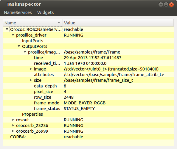
First of all use rock-display (comes with gui/vizkit) to check for available ROS services:
rock-display
Correspondingly, in a Ruby script, one can get hold of a ROS node object through the standard name service interface:
camera = Orocos.name_service.get '/prosilica_driver'
and give that to APIs that expect Orocos task, e.g. assuming that we have a stereo task which relies on image data from one ROS-driven camera (/prosilica_driver) and one Rock-driven one:
require 'orocos'
Orocos.initialize

Orocos.run 'camera_prosilica::Task' => 'right_camera', 'stereo::Task' => 'stereo' do
  left_camera  = Orocos.name_service.get '/prosilica_driver'
  right_camera = Orocos.name_service.get 'right_camera'
  stereo       = Orocos.name_service.get 'stereo'

  left_camera_frame = left_camera.find_output_port('/prosilica/image_raw')
  right_camera.frame.connect_to stereo.right_frame
  left_camera_frame.connect_to stereo.left_frame

  right_camera.configure
  stereo.configure
  right_camera.start
  stereo.start
  Orocos.watch(stereo, right_camera) # Cannot watch a ROS node
end
All the Orocos connection policies can be applied when connecting a ROS node with a Rock component.